Magnetic Field Lines


Oersted's Principle (Principle of Electromagnetism)
Whenever a charge moves through a stright conductor, a circular magnetic field will be created around the conductor. Moving electric charges produces a magnetic field.
Right-Hand Rule and Left-Hand Rule for Magnetic Field Line Direction
If you hold a straight conductor in your right hand with your right thumb pointing to the direcction of the current (direction of the positive charge), your curled fingers will point in the direction of the magnetic field lines.
If you hold a straight conductor in your left hand with your left thumb pointing to the direction of the electron flow (direction of the negative charge), your curled fingers will point in the direction of the magnetic field lines.
Magnetic fields due to currents in a long straight wire
Direction determined by RHR: grasp the wire with your right hand. If your thumb points in the direction of the current, your fingers will curl around the wire in the same direction as the magnetic field.
Strength at distance r from wire: B = μI / 2πr, where I is current, μ is the permiability of the material around the wire (in units of newtons per square ampere N/A2). In air, close to vacuum, μ = 4π * 10-7 N/A2, so we also have B = μ0I / 2πr
Solenoid & Right-Hand Rule for Solenoid
Winding a conductor into a coil containing several loops will give a solenoid. The magnetic field around a solenoid is similar to that of a bar magnet.
To determine the direction of the magnetic file lines around a solenoid, wrap the fingers of your right-hand around the coil in the direction of the conventioinal current, your right thumb will point in the direction of the north magnetic pole of the coil.
The strength of a solenoid's magnetic field can be increased by
- increasing the number of loops,
- increasing the amount of electric current,
- inlcuding a soft-iron core, or
- any combination of these.
Magnetic field strength inside the solenoid is B = μ * N/L * I, where μ is the permiability of the core, N is number of loops, L is length, and I is current.
Magnetic Force
Any MOVING charge will produce a magnetic field around it and any MOVING charge placed in an external magnetic field (however it is produced) will experience a magnetic force on it, due to the interaction of the 2 magnetic fields.
Magnetic force depends on the velocity of the charge. Gravitational and electric forces do not depend on the velocity of the charge/mass. Magnetic force is proportional to the charge and the velocity of the charge, given the external magnetic field strength.
Magnetic Force on a Free Moving Charge in a Magnetic Field
The magnetic force on a free moving charge F is perpendicular to both the velocity of the charge and the magnetic field line direction. The magnetic force direction can be given by the right hand rule. The magnetic force magnitude is given by the charge (this is a scalar quantity) times the vector product of velocity and magnetic field (intensity).
F = q * v * B * sinθ
Where q is the charge, v is the velocity of the charge, B is external magnetic field strength (q is scalar, v, B are vectors), and theta θ is the angle between v and B.
Also remember the direction of the magnetic force on a free moving charge is perpendicular to the plane formed by v and B

The right hand rule, RHR, for determining the direction of the magnetic force experienced by a moving positive charge in a magnetic field is:
- thumb points in the direction of a moving positive charge's velocity, v
- fingers point in the direction of magnetic field, B
- palm faces in the direction of the magnetic force, F
This right hand rule only applies to positive charges. You would need to use an equivalent left hand rule for electrons. Or just remember that if the force would be "up" for a positive charge, then the force will be "down" for a negative charge. That is, the force on a negative charge will always act 180º in the opposite direction.
Magnetic Force on a Current-Carrying Conductor in a Magnetic Field
Magnetic force on a current-carrying conductor in a manetic field Fm is the product of the magnetic field intensity (B, a vector), the length of the conductor (L, a scalar), the current in the conductor (I, a vector), and the sine of the angle that the electric current makes with the magnetic field vector.
Fm = I * L * B * sinθ
The right-hand rule:

Charges and Uniform Circular Motion
If a free charge moves into a magnetic field with direction perpendicular to the field, it will follow a circular path. The magnetic force, being perpendicular to the velocity, provides the centripetal force.
In the diagram below, a negatively charged particle moves in the plane of the page in a region where the magnetic field is perpendicular into the page (represented by the small circles with x’s—like the tails of arrows). The magnetic force is perpendicular to the velocity, and so velocity changes in direction but not magnitude. Uniform circular motion results.
In the below equation, r is radius of the circle, v is velocity, and m is mass of the charge.
To find the mass of the charge: m = qBr/v
Ampere's Experiment
If the current directions in 2 parallel wires are the same, then the produced magnetic field lines will go in opposite directions, and an attractive magnetic force will result. This means the 2 wires will attract each other.
If the current directions in 2 parallel wires are in different directions, then the produced magnetic field lines will go in the same direction, and an opposing magnetic force will result. This means the 2 wires will repel each other.
Unit of Magnetic Field Strength
Unit of mgnetic field strength is T for Tesla.
Formula 1: 1 T = 1 kg / C * s, where C stands for coulomb, and s stands for second.
Formula 2: 1 T = 1 N / A * m, where A stands for Ampere, and m stands for meter, and N stands for Newton.
https://en.wikipedia.org/wiki/Tesla_(unit)
Explanation of Formula 1: Remeber electric field intensity is Fe/C because Fe is proportional to C. Since Fm is proportional to both C and velocity of C, therefore, magnetic field strength/intensity = Fm / C*V = Newton / C * (m/s) = kg * (m/s2) / C * (m/s) = kg / C * s, where m is meter.
Explanation of Formula 2: This definition is based on the fact that if two 1-meter long current-carrying wire segments, each having 1 ampere of current, are either attracted to or repelled from each other by one newton of force, then the strength of the magnetic field produced by either current-carrying segment equals 1 tesla at the location of the other wire.
Direct Current Motor

Law of Electromagnetic Induction
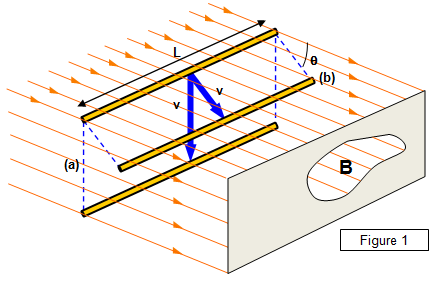
Moving a straight line conductor in a magnetic field (as shown above) will induce a potential difference between the conductor's 2 ends and if the conductor is connected to a closed circuit there will be a current in the circuit:
1. When the wire rests in the magnetic field, there is no current.
2. When the wire is moved through the field in parallel to the field (θ=0°), there is no current.
3. When the wire is moved through the field that "cuts across" the field lines at angle θ, there will be a small current
4. When the wire cuts across the field lines at right angles (θ=90°), there will be maximum current.
5. When the wire cuts across the field lines up and down, the current direction alternates.
Direction of the induced current determined by RHR rule: fingers of the right hand point in the direction of the magnetic lines; thumb points in the direction of the velocity of the wire; palm will indicate the direction of the induced current.
Induced potential difference is called called motional emf, and when the wire cuts across the magnetic field lines at right angle, we have emf = B * L * V * sinθ, where B is magnetic field intensity (Tesla), L is wire length, and V is wire velocity. For example: suppose we have a wire 0.5m long, moving at right angles to a 0.04-T magnetic field with a velocity of 5 m/s. Then the induced emf will be emf = (0.04T)(0.5m)(5m/s) = 0.1V
NOTE: emf = B * L * V * sinθ can be explained by the Faraday's law emf = -N(ΔΦ/Δt) below. Here N=1; ΔΦ/Δt = B * A * cos(90-θ) / Δt = B * L * x * sinθ / Δt = B * L * V * sinθ. Notice the θ used in emf = B * L * V * sinθ is complementary to the θ used in emf = -N(ΔΦ/Δt); also notice area A = L * x, where x is the distance by which you move the line in the direction of v.
Magnetic flux, magnetic flux density, and Faraday's law of electromagnetic induction
Suppose we have a coil made up of N turns of wire and the coil has a cross-sectional area of A. It cuts across a magnetic field with field intensity B at angle θ. Then we can define the magnetic flux Φ as Φ = B * A * cosθ.
The unit of magnetic flux is weber, 1 weber = 1 tesla square meter.

So what is magnetic flux density? Magnetic flux density is just magnetic field intensity: from Φ = B * A * cosθ, we have B = Φ / (A*cosθ), and the unit of magnetic flux density is webers per square meter (Wb/m2).
Faraday's law of electromagnetic induction states that the motional emf = -N(ΔΦ/Δt), where ΔΦ is change in magnetic flux, and Δt is change in time, and N is the number of turns of wire in the coil.
From Faraday's law, as long as there are magnetic field changes, even if there is no relative velocity between the coil and the external magnetic field, there will be induced emf.
Variations of Farady's Law
Material adapted from http://hyperphysics.phy-astr.gsu.edu/hbase/electric/farlaw2.html
In example 1, two coils are penetrated by a changing magnetic field. Magnetic flux Φ is defined by Φ=BA where B is the magnetic field or average magnetic field and A is the area perpendicular to the magnetic field. Note that for a given rate of change of the flux through the coil, the voltage generated is proportional to the number of turns N which the flux penetrates.
In example 2, the voltage is generated when a coil is moved into a magnetic field. This is sometimes called "motional emf", and is proportional to the speed with which the coil is moved into the magnetic field. That speed can be expressed in terms of the rate of change of the area which is in the magnetic field.
In example 3, we see the standard AC generator geometry where a coil of wire is rotated in a magnetic field. The rotation changes the perpendicular area of the coil with respect to the magnetic field and generates a voltage proportional to the instantaneous rate of change of the magnetic flux. For a constant rotational speed, the voltage generated is sinusoidal.
Here is another diagram for example 3:

In example 4, voltage is generated by moving a magnet toward or away from a coil of wire. With the area constant, the changing magnetic field causes a voltage to the generated. The direction or "sense" of the voltage generated is such that any resulting current produces a magnetic field opposing the change in magnetic field which created it (Lenz's law).
Lenz's Law
If a changing magnetic field induces a current in a coil, the electric current is in such a direction that its own magnetic field opposes the change that produced it.
http://hyperphysics.phy-astr.gsu.edu/hbase/magnetic/emfchb.html
DC motor and generator
https://m.youtube.com/watch?v=d_aTC0iKO68
Alternating Current
Alternating current is an electric current that periodically reverses direction. In an alternating current, voltage changes periodically between maximum positive value to maximum negative value crossing 0 value. At 0 voltage, lights will get dimmer but at around 60 cycles per secondd (60 Hz), people cannot detect them. Ohm's law is applicable to alternating current as well.
Galvanometer, Ammeter, Voltmeter
Galvanometer is made based on Motor Principle. Ammeter and voltmeter make use of galvanometer, Ohm's law, and the principles of parallel circuits.
